New printed parts and new mockup assembly
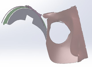
With the new 3D scan I could make a new model part that I then cut the ear piece to the complex contour of the helmet side with.
Cutting part (gray in image) created from scanned surface. This body is then used with the Cavity command in 3D Cad (may be called other names depending on CAD system used) to remove intersecting volume from the ear piece model.
I then added fasteing holes for the frame that will support the rubber neck bellows all around the lower edge of the hemet.
To further accomodate the fit of the bellows I cut the bottom inner edge as shown, this conforms to mate the curves created by the Procap helemt and visor.
I finally printed and fit the ear piece to the helmet, it was a perfect fit! :)
The next step was to re-model and print the final missing piece aka the "Bent Spark-plug" to go on the ear piece lower section. My Brother has named this part this "The Cool part". I think they're all cool if I was to name it it'd be "The Difficult bothersome part that had to be remodeled several times and then barely fit together". But yes it looks cool when finished. :)
It's modeled as four separate pieces that come together, this is to give the best possibility of sanding off print lines and still retain detailing.
I printed the parts and sanded and filed it quite a bit to fit together, then had to press it together with some force for it to finally snap in place.
This is because when you 3D print models the "holes" or rather the inside open spaces always shrink a certain percentage. I did adjust some for this but not enough. If it's a solid printed part and a simple block like most of the other parts you just scrape and sand it to get the fit you need but this is quite a complex model with fine flanges all over it making such sanding difficult if at all possible.
I should have modeled the hole contour larger (I remedied that after the print).However, it looked fine assembled but with the inner tension from that, when I acetone dipped the piece it cracked at the front.
Luckily it still fit in the slot on the ear piece and that clamped it together barely showing a crack so I decided to still use the part. It'll be removable to get at the screw points beneath it so I can re-print the part, paint up and replace easily later if I feel the need.
It did reatin plenty of detail and the finish of the piece was quite good, it looks factory moulded.
After that I fully secured the ear pice to the helmet with hidden screws, put the 3D-printed fake bolts in the screw holes (the top arc), added all the printed parts, drilled out ande deepened the rivet holes around the chamfered outer edges and mounted the rivets.
The left ear piece assembly was finally done after 2 years of modeling, printing, scanning the helmet side and re-modeling! The best thing with 3D CAD is making a new mirrored right side was quick and easy work.
Now all modeling is done except some re-work of the chin light and I can leave that to last and just print the remaining pieces, smooth, paint and assemble it all.
I started printing the right side ear piece body after making sure the left side was as I wanted it. It's a 3 day print at the highest precision and thinnest layer setting for the best result possible.
Here's a photo with flash showing the metal paint parts gleam. It'll look nice on cosplay photos. It'll look even better when I finish painting it all. ;)


